Water Reservoir Maintenance - Roof Stormwater and Gutter Works
Overview of Project:
The Scope of this project is to design and construct roof gutters and stormwater systems for two water reservoirs and flooring replacement at adjacent water pump station
Scope of Works:
Gutter System
The eaves gutter system will be designed in accordance with AS/NZS 3500.3 Plumbing and Drainage – Stormwater Drainage and based on 5-minute rainfall intensities on a 20-year average recurrence interval.
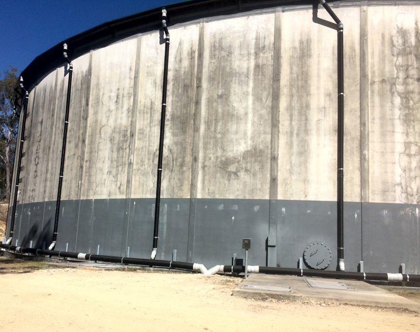
To facilitate handling and allow greater spans, the gutter will be composed of C15019 purlin orientated about the weak axis. The purlin will be blasted and painted to ensure galvanic compatibility with the existing Colourbond Trimdek roof sheeting. A rain-header will couple 2 OFF 6000 LG purlins. The tank circumference is approximately 160 m (51 m ID), resulting in a total of approximately 14 rain headers and downpipes. Note that at a length of 6 metres, the radial deviation from the 51 m diameter tank is about 175 mm.
The C15019 purlin will be spaced a minimum of 300 from the vermin proofing. As per the client’s specifications, all gutter elements will have a minimum fall of 2 degrees. To limit deflection in the C15019 purlin to Span / 300 (which is recommended in AS1170.0 for roof members) the distance between simple supports shall be less than 4 metres. Practically, this means that the gutter shall be fixed at each 100×6 SHS post, which supports the radiused 150 x 90 x 10 UA. The gutter fixing bracket will be bolted to the 100×6 SHS post with 2x M12 GR8.8 Galvanised fasteners.
A 600 wide x 2400 LG Colourbond flat sheet will be used to span between the edge of the existing roof and the new purlin gutter. The flat sheet will be fixed with the existing crest-fixings in the Trimdek sheet, and Tek-screwed to the top flange of the C15019 purlin.
In accordance with the Lysaght Roofing and Walling Installation Manual (2013) the sheet will lap under the existing Trimdek sheeting by 300 mm. The cavity formed between the Trimdek profile and the flat Colourbond sheet should be filled by a foam infill closure strip.
Downpipes
The downpipes will be designed in accordance with AS/NZS 3500.3 Plumbing and Drainage – Stormwater Drainage and based on 5-minute rainfall intensities on a 20 year average recurrence interval.
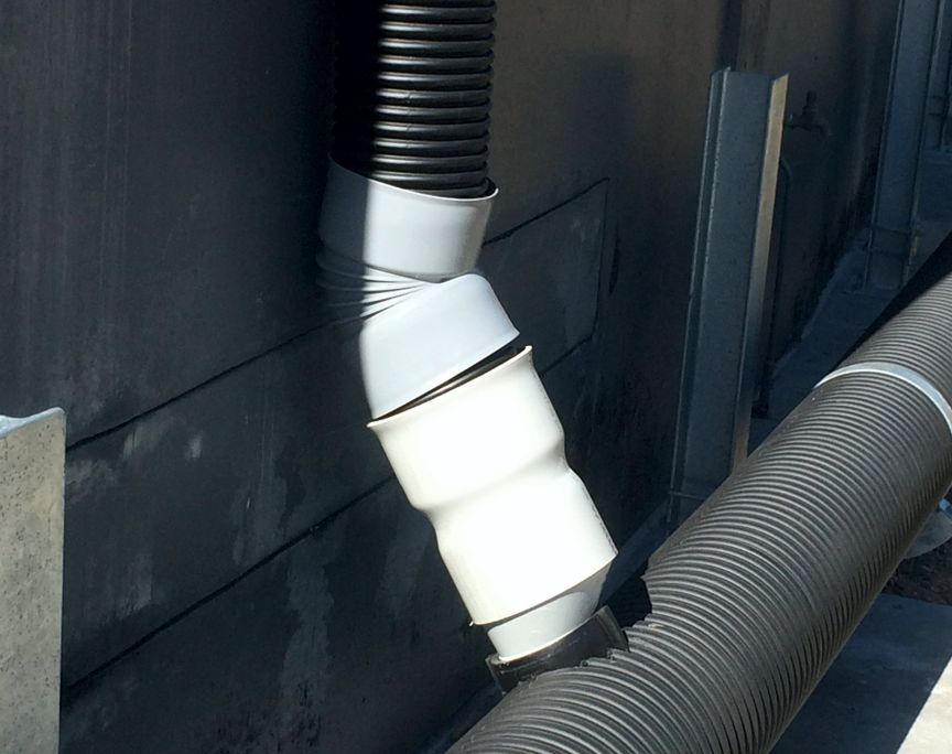
The downpipes will be constructed of Colourbond steel to match the gutter and existing colour scheme and will be mitred at 45 degrees at the ring main end to ensure smooth flow of the water between the two.
As discussed above, there will be a total of 14 downpipes. 100 mm downpipes should be acceptable. These will be fixed to the rain header with Tek screws and into the tank wall (for support during wind events) with 6×50 ‘Knock-In’ Anchors at 3 m CRS.
Ring-Main
The ring-main will be constructed of DN225 DWV Sewer Pipe RRJ pipe which utilises rubber ring joints and is considerably cheaper than PVC-M PN 12 pipe. These pipes are available in 3 m lengths. The ‘wrap’ around the 51m diameter tank will be achieved by joining the 3 m straight lengths of pipe with fabricated bends (female and female) to suit.
The ring-main shall be supported on saddles at a maximum of 2.6 m spacings (recommended in Vinidex catalogue). The saddles will be of similar construction to the figure below and shall withstand all thrust loads and dead loads.
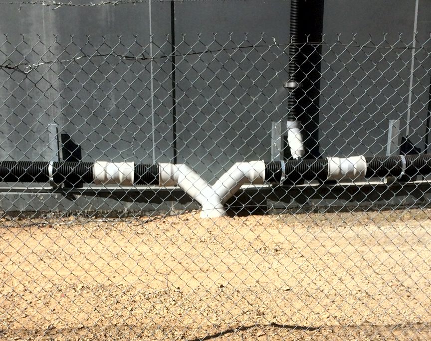
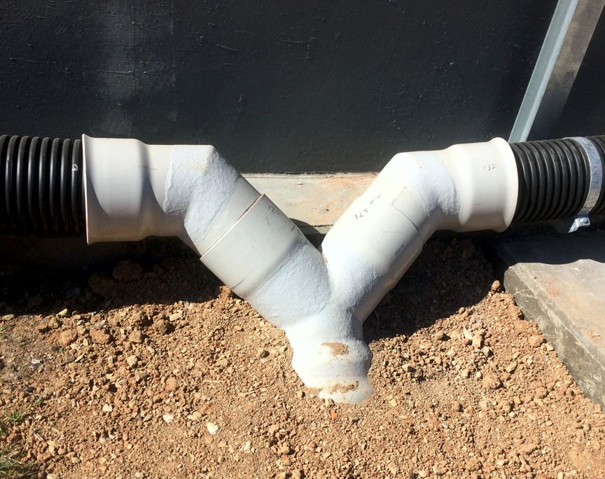
The 100 mm downpipe will run into a 225x 100 45o sewer junction (female and female) to promote smooth flow.
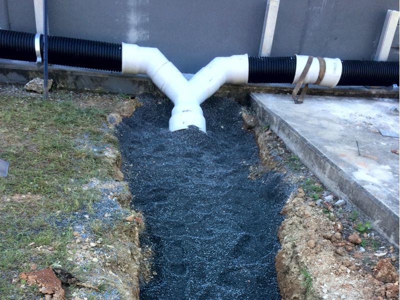
PE Pipe Ring Main
The ring main will be constructed of 250 Outside Diameter SDR11 PN4 PE100 Black pipe. The pipe will be bent to a radius that lands it on the heel of the reservoir slab and fixed to the slab with saddles as described in the figure above. Note that the saddle away from the main ‘tee’ will allow sliding due to thermal expansion / contraction. Alternatively, could use standard flexistrut saddle clamps bolted to a folded 3 mm or 5 mm sheet to allow for height variation.
Where the 100 mm downpipe runs into the ringmain, a 45o equal tee (PE100) will be electrofusion welded into the line. The branch of the equal tee will have a 225 x 110 reducer welded on to reduce the clearance around the 100 mm downpipe.
Road Pump Station Flooring
Following cutting of the concrete slab and vacuum excavation of all sand and material 4 OFF 75×4 SHS portal frames with 8 PL cleats will be installed in the pit at equal spacing (assuming this avoids existing pipe spools). Each SHS leg will be anchored to the concrete with M10 GR4.6 galvanised threaded rod and an injectable mortar such as HILT HIT HY-200. Baseplates will be sized to minimise any punching shear in the concrete.
150 PFC will span between the SHS portals. Assuming human traffic only (2.5 kPa platform loads) C255MPG Webforge grid mesh will be acceptable for spans up to 1200. Grid mesh can then be fastened to flange of the 150 PFC with C001MG fixing clips.
Where required, the grid mesh will be contain cut-outs to avoid clashing with existing pipe spools. These cut-outs will be edge-banded to maintain the structural integrity of the grid mesh.
Gutter Access System
A system will be designed to allow safe access to gutters for regular maintenance/cleaning. The system offered is the Sayfa Travel 8 System which is a Stainless Steel proprietary engineered system designed and tested meeting the Australian Standard AS/NZS1891.2 for Horizontal Life-Lines.
The system fixes to the exterior of the cladding with 8mm self-sealing structural rivets and a neoprene sealing strip between the support plates and the cladding. (this technique guarantees water proofing and dissimilar metal contact).
Conclusion/Outcome:
The project was completed on time and on budget. The client Water was happy with the works completed.